Thursday 15 March 2007

Why do Golf balls have dimples?

Golf Ball Dimples & Drag


    Can you explain why a golf ball has dimples? If dimples reduce drag, why don't we see this surface feature on other aerodynamic shapes like airplane wings?
    - question from Brent Obst & Andrew
While few among us can deny that golf is one of the least exciting of all spectator sports, we aerospace engineers are fascinated by its aerodynamics! Even the non-golfers of the world are familiar with the shape of a golf ball, like that pictured below, and have probably wondered why its surface is covered with small indentations called dimples.

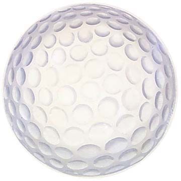
The dimples of a typical golf ball

Before explaining the purpose of dimples, we first need to understand the aerodynamic properties of a sphere. Let us start by looking at a smooth sphere without any dimples, like a ping-pong ball. If we lived in an ideal world without any friction, the air flowing around a smooth sphere would behave like that shown in the following diagram. In this figure, the angle q represents position along the surface of the sphere. The leading edge of the sphere that first encounters the incoming airflow is at q=0° while the trailing edge is at q=180°. A position of q=90° is the top of the sphere, q=270° is the bottom, and q=360° brings us back around to the leading edge. Note that in this ideal situation, the air flowing around the sphere forms a perfectly symmetrical pattern. The streamline pattern around the front face, from 270° up to 90°, is the same as that around the back face, from 90° down to 270°.

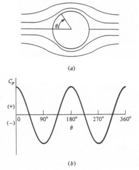
(a) Ideal frictionless flowfield around a sphere and (b) the resulting pressure distribution

The lower half of this figure also displays the pressure distribution around the surface of the sphere, as represented by the non-dimensional pressure coefficient Cp. Positive (+) values of Cp indicate high pressure while negative (-) values indicate low pressure. It is the differences between high-pressure regions and low-pressure regions that create aerodynamic forces on a body, like lift and drag.

However, this ideal flow pattern tells us something very interesting. Notice that the pressure at the front of the sphere, or q=0°, is very high. This high pressure indicates that the incoming air impacting against the front face creates a drag force. Nonetheless, the pressure at the back of the sphere, or q=180°, is also high and identical to that at the front. This high pressure actually creates a thrust, or negative drag, that cancels out the drag on the front of the sphere. In other words, this theoretical situation tells us that there is no drag on a sphere!

Early aerodynamics researchers were quite puzzled by this theoretical result because it contradicted experimental measurements indicating that a sphere does generate drag. The conflict between theory and experiment was one of the great mysteries of the late 19th century that became known as d'Alembert's Paradox, named for famous French mathematician and physicist Jean le Rond d'Alembert (1717-1783) who first discovered the discrepancy.

The reason d'Alembert's ideal theory failed to explain the true aerodynamic behavior of a sphere is that he ignored the influence of friction in his calculations. The actual flowfield around a sphere looks much different than his theory predicts because friction causes a phenomenon known as flow separation. We can better understand this effect by studying the following diagram of the actual flow around a smooth sphere. Here we see that the flowfield around the sphere is no longer symmetrical. Whereas the flow around the ideal sphere continued to follow the surface along the entire rear face, the actual flow no longer does so. When the airflow follows along the surface, we say that the flow is attached. The point at which the flow breaks away from the surface is called the separation point, and the flow downstream of this point is referred to as separated. The region of separated flow is dominated by unsteady, recirculating vortices that create a wake.

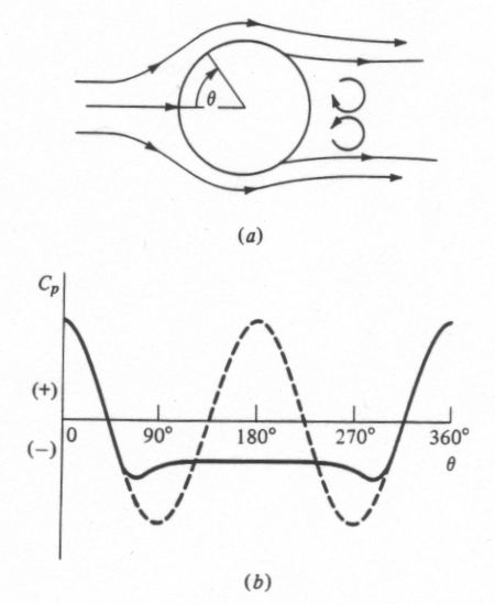
(a) Actual separated flowfield around a sphere and (b) the resulting pressure distribution

The cause of this separation can be seen in the above pressure distribution around the sphere. As the flow moves downstream from the q=90° or q=270° position, it encounters an increasing pressure. Whenever a flow encounters increasing pressure, we say that it experiences an adverse pressure gradient. The change in pressure is called adverse because it causes the airflow to slow down and lose momentum. As the pressure continues to increase, the flow continues to slow down until it reaches a speed of zero. It is at this point that the air no longer has any forward momentum, so it separates from the surface.

Once the flow separates from the surface, it no longer results in the ideal pressure distribution shown as the dashed line. Instead, a separated flow creates a region of low pressure in the wake. We see this behavior over the rear face of the sphere from 90° < q <>. Here, the actual pressure distribution, shown as the solid line, remains negative, in contrast to the ideal prediction. The pressure on the front face is still high, however, just as it was for the ideal sphere. Since the pressure is now much higher on the front face than it is on the rear face, the net result is a drag force exerted on the sphere. By accounting for the effect of friction, theory and experiment come into agreement and d'Alembert's Paradox is reconciled.

This explanation leads us to an important conclusion: the drag on a sphere is dominated by the flow separation over its rear face. If we could somehow minimize that separation, the drag experienced by the sphere would be significantly reduced. We can see this effect in experimental data, like that pictured below.

Variation of drag coefficient with Reynolds number for a sphere

This diagram illustrates how the drag of a sphere varies with the Reynolds number. Reynolds number (Re) is an important non-dimensional parameter that is used to relate the size of an object to the flow conditions it experiences, and is defined by the equation

where

    r = atmospheric density
    V¥ = velocity
    l = reference length (in the case of a sphere, this variable is defined as the diameter)
    m = viscosity (or friction)
In other words, any two spheres that experience the same Reynolds number should exhibit the same aerodynamic characteristics even if the spheres are of different sizes or flying at different speeds. The above figure indicates that there is a significant change in the drag on a smooth sphere at a Reynolds number of about 3x10⁵. Below this Re, the drag coefficient is roughly constant at 0.5. Above this Re, the drag coefficient again becomes nearly constant at about 0.1.

What is it about this particular Reynolds number that causes such a large reduction in drag? It turns out that it is at this critical point that the air flowing around the sphere makes an important change. We have already discussed the concept of flow separation. One of the key factors affecting flow separation is the behavior of the boundary layer. The boundary layer is a thin layer of air that lies very close to the surface of a body in motion. It is within this layer that the adverse pressure gradient develops that causes the airflow to separate from the surface.

At low Reynolds numbers, the boundary layer remains very smooth and is called laminar. Laminar boundary layers are normally very desirable because they reduce drag on most shapes. Unfortunately, laminar boundary layers are also very fragile and separate from the surface of a body very easily when they encounter an adverse pressure gradient. This separated flow is what causes the drag to remain so high below the critical Reynolds number.

At that Reynolds number, however, the boundary layer switches from being laminar to turbulent. The location at which this change in the boundary layer occurs is called the transition point. A turbulent boundary layer causes mixing of the air near the surface that normally results in higher drag. However, the advantage of turbulence is that it speeds up the airflow and gives it more forward momentum. As a result, the boundary layer resists the adverse pressure gradient much longer before it separates from the surface.

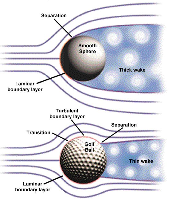
Flow separation on a sphere with a laminar versus turbulent boundary layer

The difference in the flowfields around a smooth sphere and a rough, or dimpled, sphere can be seen above. Since the laminar boundary layer around the smooth sphere separates so rapidly, it creates a very large wake over the entire rear face. This large wake maximizes the region of low pressure and, therefore, results in the maximum difference in pressure between the front and rear faces. As we have seen, this difference creates a large drag like that seen below the transition Reynolds number.

The transition to a turbulent boundary layer, on the other hand, adds energy to the flow allowing it to remain attached to the surface of the sphere further aft. Since separation is delayed, the resulting wake is much narrower. This thin wake reduces the low-pressure region on the rear face and reduces the difference in pressure between the front and back of the sphere. This smaller difference in pressure creates a smaller drag force comparable to that seen above the transition Reynolds number.

These results tell us that causing a turbulent boundary layer to form on the front surface significantly reduces the sphere's drag. For a given sphere diameter, a designer has only two options encourage this transition, either 1) increase the speed of the flow over the sphere to increase the Reynolds number beyond transition or 2) make the surface rough in order to create turbulence. The latter case is often referred to as "tripping" the boundary layer.

In the case of a golf ball, increasing the speed is not an option since a golfer can only swing the club so fast, and this velocity is insufficient to exceed the transition Reynolds number. That leaves tripping the boundary layer as the only realistic alternative to reducing the drag on a golf ball. The purpose of the dimples is to do just that--to create a rough surface that promotes an early transition to a turbulent boundary layer. This turbulence helps the flow remain attached to the surface of the ball and reduces the size of the separated wake so as to reduce the drag it generates in flight. When the drag is reduced, the ball flies farther. Some golf ball manufacturers have even started including dimples with sharp corners rather than circular dimples since research indicates that these polygonal shapes reduce drag even more.

Comparison of flow separation and drag on blunt and streamlined shapes

The reason we do not see dimples on other shapes, like wings, is that these particular forms of boundary layer trips only work well on a blunt body like a sphere or a cylinder. The most dominant form of drag on these kinds of shapes is caused by pressure, as we have seen throughout this discussion. More streamlined shapes like the airfoils used on wings are dominated by a different kind of drag called skin friction drag. These streamlined bodies, like that pictured above, have a teardrop shape that creates a much more gradual adverse pressure gradient. This less severe gradient promotes attached flow much further along the body that eliminates flow separation, or at least delays it until very near the trailing edge. The resulting wake is therefore very small and generates very little pressure drag.

However, there do exist other types of devices commonly used on wings that create a similar effect to the dimples used on golf balls. Though these wing devices also create turbulence in order to delay flow separation, the purpose is not to decrease drag but to increase lift. One of the most popular of these devices is the vortex generator.

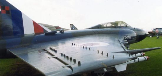
A Gloster Javelin showing the three sets of vortex generators located along the outer portion of the wing

Vortex generators are often placed along the outer portion of a wing in order to promote a turbulent boundary layer that adds forward momentum to the flow. As in the case of the golf ball, this turbulent boundary layer helps the flow overcome an adverse pressure gradient and remain attached to the surface longer than it would otherwise.

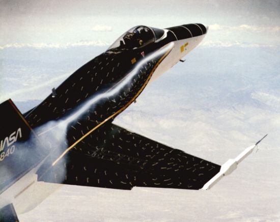
Flow visualization test on the leading edge extension of an F-18

A related device that is most commonly used on high performance fighters is the leading edge extension (LEX), like that shown above. Both the vortex generator and the LEX are primarily used to delay the flow separation that occurs when operating at high angles of attack near stall. As angle of attack increases, the adverse pressure gradient along the airfoil becomes increasingly stronger. Once the stall angle is reached, the gradient becomes so strong that it forces the flow to separate resulting in a loss of lift or control effectiveness. The advantage of devices like vortex generators and leading edge extensions is that they force the flow to remain attached at higher angles of attack and increase the stall angle. This improvement gives planes likes fighters greater maneuverability while increasing the safety of commercial airliners.
- answer by Jeff Scott, 13 February 2005

Aerospace at Queen-Marry university of london.

Aerospace Engineering


image - Eng

Introduction
Aerospace technology has grown out of the problems of design, construction, and operation of vehicles that manoeuvre above the Earth's surface - ground-effect machines, helicopters, aircraft and spacecraft. Design of such vehicles has always been challenging, because they operate in a hostile environment, and also because they have to be lightweight, efficient and reliable. These same requirements apply not only to future spacecraft and high performance transport aircraft, but also to the next generation of ground transportation, such as high-speed trains, cars, over-water transportation, sport vehicles. Future work is anticipated in zero gravity and manufacturing of high-purity materials and medicines, and the design of solar-powered satellites.

Aerospace engineering is a field where state-of-the-art technologies are applied every day. It is an exciting profession with outstanding career opportunities in which physical sciences, mathematics and computers are combined in the design of air and space vehicle systems and components to achieve high performance with limited size and weight. This requires aerospace engineers to constantly develop and apply the most advanced technologies.

Given the rapid developments in aerospace technology, the Department's overall goal is to teach you how to respond to these changes and advance with them. Teaching is directed not only towards securing you a job in the aerospace industry when you complete the course, but also providing a springboard to research and management positions in civil and military aviation, not to mention careers in government.

The Department offers:

  • four-year full-time MEng in Aerospace Engineering, H420
  • four-year full-time MEng in Aerospace Systems, H425
  • three-year full-time BEng in Aerospace Engineering, H421
  • four-year sandwich BEng in Aerospace Engineering, H422
  • three-year full-time BEng in Avionics HH45

The curriculum development for Aerospace students is based on carefully selected goals for the educational program and is closely linked to the needs of aerospace industry. The overall goal is to train engineers who are able to respond to the rapid developments in aerospace technology. Training is directed towards future top positions, not only in the aerospace industry and research institutions, but also in other engineering fields. This programme aims to satisfy the requirements of industry and at the same time be interesting and rewarding to the student. Training in workshop practice, which is an essential requirement for accreditation by IMechE & Royal Aeronautical Society is provided via a field course.

After studying the Aspect of Aerospace Design course in the first year, students specialise in aerospace engineering in the second and third years. One popular activity is attendance at the Flight Testing short course at Cranfield College of Aeronautics, where in-flight experiments are conducted in an instrumented Jet stream aircraft. Taking readings from instruments while the aircraft is undergoing a stall is an enlightening experience! A popular feature of this programme is the individual project, which is carried out throughout the final year. This may be a detailed design study, an experimental and/or theoretical investigation. Projects we have run include: helicopter control and development of a control system, effects of expansion waves on the structure of a supersonic turbulent boundary layer, and wing tip propulsion for induced drag reduction.

Students on the sandwich course will spend their third year working in industry either in the UK or abroad. The Department assists in finding placements for these students.

The four-year MEng Aerospace Engineering programme enables broader and deeper study in specialist topics during the fourth year. The fourth year includes an MEng project, a full course-unit of aerospace design, theoretical courses in aerodynamics, computational mechanics and computational fluid dynamics. All students on this programme undertake a group design project in their final year which emphasises the benefits of teamwork in tackling complex problems.

Top of page

Course outline

Year 1
  • Aero Eng Design
  • Stress Analysis
  • Computing & Statistics
  • Mechanics of Fluids
  • Dynamics
  • Thermodynamics
  • Engineering Maths
Year 2
  • Classical Aerodynamics
  • Electrical Technology
  • Engineering Maths
  • Structural Analysis
  • Mechanics of Fluids 2
  • Vibration and Control
  • Design
  • Communication, Design and Manufacture
Year 3
  • Research Project
  • Applied Aerodynamics
  • Aerospace structures
  • Stability and Control
  • Spacecraft Design
  • Maintenance Planning
  • Aircraft Propulsion
  • Op and Fin Management
Aerospace Design
Year 4
  • Group Project
  • Computational Engineering
  • Advanced Spacecraft Design
  • Aerospace Design
  • Computational Fluid Dynamics
  • Advanced Aerodynamics

Top of page

Research Projects

  • Modelling of the forward fuselage of the Project Orion Aircraft

As part of 4th year projects, students are developing a derivative (powered) aircraft: Project Orion. In an effort to accelerate progress to permit flight testing in 2003/4, three extra independent third year projects are set this year. This project would involve reverse engineering in order to arrive at a sufficiently representative CAD model of the forward fuselage of the aircraft, which is based on an EA9 Kit Glider presently in Whitehead Laboratory. The modelling package will be IDEAS. The aim is to produce a 3-D model of the forward fuselage (to permit further design work), and to derive an estimate of the moments of inertia etc. If time permits, then further design work on the forward fuselage can be initiated (such as the design and fitting of the canopy) and the CAD model of the fuselage exterior might later be used to produce a wind tunnel model. Before the project can properly commence, however, it should be noted that some time will be needed to gain experience with the IDEAS modelling and mechanisms software using self-learn tutorials. This project would particularly suit students who think they may wish to continue working on Project Orion in their 4th year.

  • Aerodynamics of low aspect ratio wings

Recently a US entrepreneur called Wernicke proposed a new aircraft concept with low aspect wings and large large wing fences, prompting the following: a project to investigate the aerodynamics of low aspect ratio monoplane wings. In Semester A, a set of wings would be tested with various aspect ratios, less than about 3. The lift and drag of each wing would measured for different angles of attack and Reynolds numbers, with and without transition trips. Attention will then be paid to the influence of different wing tips and end plates - in order to verify data in a book by S. F. Hoerner "Fluid Dynamic Drag" - in the library.

  • Subsonic aerodynamics of re-entry lifting bodies

In the past NASA and ESA have proposed many different winged re-entry vehicle shapes with large curvature "lifting bodies" shapes, such as the M2-F2, Hermes, X-38 etc., which all had relatively low lift-over-drag (L/D) ratios at subsonic airspeeds. The objective of this study would be to find-out which shapes had the best L/D ratios. One such lifting body shape has been made and is ready for testing in Tunnel 2. Other shapes may also be tested, after a literature review has been undertaken.

  • Aerodynamics of airships

Several ellipsoidal bodies of revolution have been made and are ready for testing in Tunnel 2. The aim of this project would be compare previous experimental results of a 4:1 length/diameter body with other bodies either a 2/3:1 body or a double-ellipsoid similar to the hull design of the ATG Skycat. See www.airship.com for more background information. Generally the main design aim is to reduce the drag coefficient, based on a reference area: the volume of the body raised to the power 2/3.

  • Design of thrust micro-balance for spacecraft electric propulsion unit

Research work on a colloid nano thruster is currently underway which will produce a thrust magnitude in the order of a few mN. One test of the system will be the measurement of thrust in vacuum. The objectives of this project are therefore to review the possible methods for determining thrust from such a device recognizing the particular problems of the supply of services to the thruster (high voltage electricity and fluid feed), and to produce a detailed outline design of the thrust stand.

Initially a literature review will be undertaken, and specific reference to designs of thrust balances at NASA, RAL and QinetiQ. Following this a trade off of the potential solutions will be undertaken identifying measurement noise sources. Finally a fully detailed paper design will be produced using the IDEAS package. It is not anticipated that any manufacture will take place during this project, unless very rapid progress is made by the student.

  • Modelling of an evaporating droplet in vacuum with an applied electric field

Spacecraft colloid electric propulsion functions by accelerating small charged droplets of fluid to a high velocity in an electrostatic field. The thrust that is generated arises throughout this acceleration process and hence it is important to understand the way in which the mass of the droplet changes due to evaporation. The objective of this project is to develop a simple model of the general evaporation process which may lead at certain times to the break-up of the droplet due to electrostatic forces. Initially a literature review will be undertaken to identify the key processes which take place for an uncharged fluid droplet introduced into vacuum. The changes to this basic situation when there are additional electrostatic (Coulombic) forces of the charge in the droplet will also be part of this review. A thermodynamic model of the evaporation process will then be developed from a theoretical viewpoint. A simple numerical model of principal features of this model will be developed.

  • Spacecraft tethers

The possibility of using tethers in space have been identified as a method for both changing the orbit of a satellite or as a method of generation of power for the satellite. There was recently a test of a tether system on board the shuttle which demonstrated some problems with the deployment mechanism. The objective of this project is to review the available literature on the subject of tethers and identify realistic opportunities in space for this technology.

  • Colloid thruster noise modelling

A spacecraft electric colloid thruster consists of an array of miniature emitters which produce a fine spray of charged particles. Various parametric models are available which describe the key factors of this spray. One application of these propulsion units which is of great interest is their use for space missions which have a very high degree of accuracy in the thrust delivered -such as the LISA mission. In this project the various thrust noise sources such as flow stability, and acceleration potential variation will be identified and their impact upon performance evaluated. The objective of the project is therefore to develop a spread sheet model to identify the noise from a colloid electric thruster array. Initially a review of the literature on colloid thrusters will be undertaken together with a review of the electrospray process. The simplest model available will then be used to develop the parametric sensitivity of a thruster array. A random fluctuation of the performance within the array of individual emitters will be used to develop a noise spectrum from the thruster.

  • Particle Dynamics

Low altitude airplanes and helicopters are particularly vulnerable to sand entering the engine and causing a severe damage. This year project concentrates on reviewing the role of External Air Particle Separators (EAPS) in preventing such damage and in simple particle dynamics. In a follow up project, the student is expected to look deeper into the role of particle dynamics in filter elements by using an existing Fortran program and extending it to 3D or including the effect of rigid surfaces. Simple flow visualization using Excel or Harvard chart is required.

  • Active noise control

Noise suppression has become essential nowadays due to increase in aircraft traffic and use of heavy machinery. One way to suppress undesired sound is to generate anti-sound. These are sound waves that when interact with the noise, destroy it. Such a technique is used in passenger cabins of airliners and lately in headphones sold for home use. In the project, the student will review the different configurations of active suppressors used in aerospace systems, the models used for the design and the performance of the suppressers. Optionally the student will solve a simplified model to beef up his/her analysis of the noise suppression.

  • Ejector seat dynamics

Ejector seat today is a crucial item in jet fighters. However, its design is still a major engineering task. In the project the student is required to review existing ejector seat installations and their operations. Additionally, the student is required to carry out trajectory calculations using simple design formulas or simulations.

Top of page

Facilities

Laboratory facilities
The Whitehead Aeronautical Laboratory has excellent wind tunnel facilities related to the different aspects of aerospace engineering. This includes several low speed, transonic and supersonic wind tunnels.

Wind tunnel facilities are complemented by measurement devices such as pressure probes, hot-wire anemometers, Laser Doppler Velocimeters, 3 and 6-components balance system for the direct measurement of force and moments, and state of the art Computer Based Data Acquisition and Processing System. Our experimental facilities also include the use of surface oil visualisation and the application of shear-sensitive liquid crystals for the detection of transitional flows. Real-Time Highly focussed schlieren system and standard colord schlieren system are being used for flow visualisation in high-speed flows.

Computer facilities
Sophisticated software is increasingly used to solve engineering design problems and our students have access to industry standard packages. These are supported by more than 350 personal computers and a range of UNIX workstations, dedicated data gathering and analysis computers.

Because of the Department's excellent reputation in computational aerospace structures and computational aerodynamics, we have been awarded a substantial grant for a dual-cluster high performance parallel computer. This makes our department among the first academic centres in Europe to acquire such a high performance computing facilities.

Another major activity in our department is design of aerospace structures and our experts work closely with Airbus industry, Eurocopter, NLR, EDAS and British Aerospace.

Top of page

Career opportunities
A central concern to choosing a career is determining the potential for employment in that profession. During the early 1990's, government funding cutbacks and a recession in the commercial airline industry forced many aerospace corporations to consolidate and reduce their workforce. These factors also led to declining enrolments at aerospace engineering schools. In fact, decreases in enrolment actually outpaced workforce reductions. However, the downturn in the aerospace industry has ended. Current trends and projections indicate a very prosperous future for our industry. In fact almost all our last year MEng graduates were able to find jobs in industries such as Rolls-Royce, Air Bus, British Aerospace, Ford Car Industries and Ministry of Defence. See here some of our graduates now in leading aersospace and aviation positions, higher degrees and research projects, general engineering positions and engineering business positions.

Overall employment prospects for Engineers are extremely good, with more than 98 per cent employed six months after graduation. Recent graduates who have started work in the Engineering industry started on annual salaries in the region of £19,000. You might expect, as a successful Engineer to be earning £30,000 to £35,000 between five and ten years after graduation.

Top of page

Industrial Links & Collaboration (Aerospace)
The department has links and collaboration through its teaching and research activities with many of the leading Aerospace Industries and Agencies worldwide. They include:

UK

  • Airbus, UK
  • Astrium
  • BAe Systems
  • British National Space Centre
  • dstl (formerly DERA)
  • QinetiQ (formerly DERA)
  • Marshalls Aerospace
  • Rolls-Royce plc
  • Rutherford Appleton Laboratories
  • SSTL

Italy

  • Alenia

The Netherlands

  • NLR
  • European Space Agency (ESA)

Germany

  • Airbus Deutschland
  • EDAS - DASA

USA

  • Boeing
  • US Air Force

Spain

  • CASA
  • EDAS CASA

France

  • Eurocopter
  • EDAS Airbus Aerospatiale
  • EDAS CCR